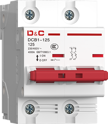
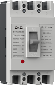
| Test | Type | Test Current | Initial State | Tripping/Non-tripping Time Limits | Expected Results | Remark |
| a | C,D | 1.13In | Initial State | t ≥ 1h | Non-Tripping | |
| b | C,D | 1.45In | Follow a | t < 1h | Tripping | |
| c | C,D | 2.55In | Code State | 1s < t < 60s (In ≤ 32A) 1s < t < 120s (In> 32A) |
Tripping | The current steadily rises to the specified value within 5 seconds. |
| d | C | 5In | Code State | t ≥ 0.1s | Non-Tripping | Turn on the current by closing the auxiliary switch. |
| D | 10In | |||||
| e | C | 10In | Code State | t ≥ 0.1s | Tripping | Turn on the current by closing the auxiliary switch. |
| D | 14In |
The circuit breaker features an advanced structure, reliable performance, high breaking capacity, and a compact, aesthetically pleasing design. All internal components are precisely positioned within a plastic housing. The housing is made of high-strength,arc-resistant, and flame-retardant material, ensuring excellent impact resistance and flame-retardant properties. The contact system utilizes an electrodynamic repulsion mechanism, providing an effective current-limiting function and significantly enhancing the breaking capacity. The tripping unit adopts an electromagnetic release (solenoid type), ensuring accurate and stable tripping current.
Multi-pole models are assembled from individual single-pole units. • The circuit breaker is designed for use by non-specialized personnel and requires no maintenance. The protective characteristicsof the overcurrent tripping unit are factory-set and cannot be adjusted by the user, ensuring consistent performance.
• The circuit breaker is designed to accommodate the side-mounting of various accessories, such as earth leakage trip units, shunt trip units, auxiliary contacts, alarm contacts, and similar components.
• The terminal connection accommodates copper conductors with a cross-sectional area of up to 25 mm². The mounting rail is a TH35-7.5 standard DIN rail.
Power Distribution
Power Distribution
Power Distribution

